How do you work in topology optimization?
Topology optimization is a powerful computational method that fundamentally changes how engineers approach design, moving away from traditional subtractive or formative thinking toward material distribution driven purely by performance requirements. At its heart, the goal is simple yet profound: to find the best possible material layout within a specified design space to meet a set of defined performance criteria, often resulting in structures that are significantly lighter and stiffer than conventional designs. Whether the objective is to maximize stiffness for a given volume of material or minimize the volume required to maintain a specific level of structural integrity, topology optimization helps uncover geometries that human intuition alone might overlook. This process is often associated with finding highly efficient, organic forms, making it a cornerstone technique in modern digital engineering workflows.
# Conceptual Engine
The process of topology optimization isn't just about removing excess; it’s about solving a complex mathematical problem iteratively. Unlike traditional modeling where you start with a solid block and remove material, or generative design which builds up from scratch based on rules, topology optimization typically starts with a full volume—the design space—that you are allowed to use. Within this space, the software then calculates the optimal arrangement of material, often by treating the material density as a continuous variable that can range from zero (no material) to one (fully solid).
The mathematical backbone often relies on what are called density-based methods. In these methods, the structural response of every tiny element, or element, within the design space is constantly evaluated under the applied loads. If an element is shown to contribute very little to the overall stiffness—perhaps it experiences near-zero stress or strain—the algorithm assigns it a lower density value, effectively flagging it for removal in the next iteration. Conversely, areas critical to load transfer or stiffness receive a higher material designation. This cycle repeats, refining the structure incrementally until the change between iterations becomes negligible or a specific termination criterion is met. The result is a highly optimized lattice or skeletal structure where material is placed precisely where it is needed most to resist the forces acting upon it.
# Setting Parameters

Working effectively in topology optimization requires meticulous setup, as the quality of the output is entirely dependent on the constraints and loads you provide. This initial phase is perhaps the most critical, turning an abstract mathematical goal into a solvable engineering problem.
# Defining Space
The first step involves establishing the design space. This is the bounding box or volume within which the final shape must reside. It’s crucial to distinguish the design space from non-design regions. Non-design regions are areas that must remain fixed and material-filled throughout the entire optimization process—think of mounting points, bolt holes, or critical interfaces where the part connects to a larger assembly. If you fail to define these fixed regions correctly, the optimizer might eliminate the very holes needed to attach the part to the machine.
# Loads and Constraints
Next, you must clearly define the environmental and operational parameters.
- Loads: What forces will the part experience? This could be static forces, pressure, acceleration (like gravity or vibration), or thermal loads. These must be applied accurately to the model.
- Boundary Conditions: Where is the part fixed or supported? These are the constraints that prevent the structure from simply moving or rotating away under load.
A common goal in structural optimization is to minimize compliance, which is mathematically equivalent to maximizing stiffness under the given loading scenario. Therefore, setting appropriate loads and fixities directly governs the resulting optimized shape.
# Manufacturing Input
This is where the computational design meets physical reality, and it’s an area where engineers must exercise significant judgment. A purely mathematically optimal structure might feature impossibly thin walls, sharp internal corners, or overhangs that cannot be supported during manufacturing.
Modern optimization software integrates manufacturing constraints directly into the iterative solver. For instance, if you plan to use additive manufacturing (AM), you might set a minimum feature size or a maximum overhang angle. If the material is intended for casting or machining, the constraints would shift to include draft angles or tool accessibility. It is essential to recognize that the choice of manufacturing method fundamentally dictates the achievable complexity and final functional viability of the topology optimized design; a shape optimized for metal powder bed fusion will look drastically different from one optimized for CNC milling, even under identical loading conditions. Ignoring these physical limitations will yield a beautiful, mathematically correct blueprint that cannot be produced cost-effectively, if at all.

# Executing the Calculation
Once the design space, loads, constraints, and manufacturing parameters are set, the actual optimization run begins. This involves selecting the appropriate solver settings and monitoring the process.
# Solver Selection
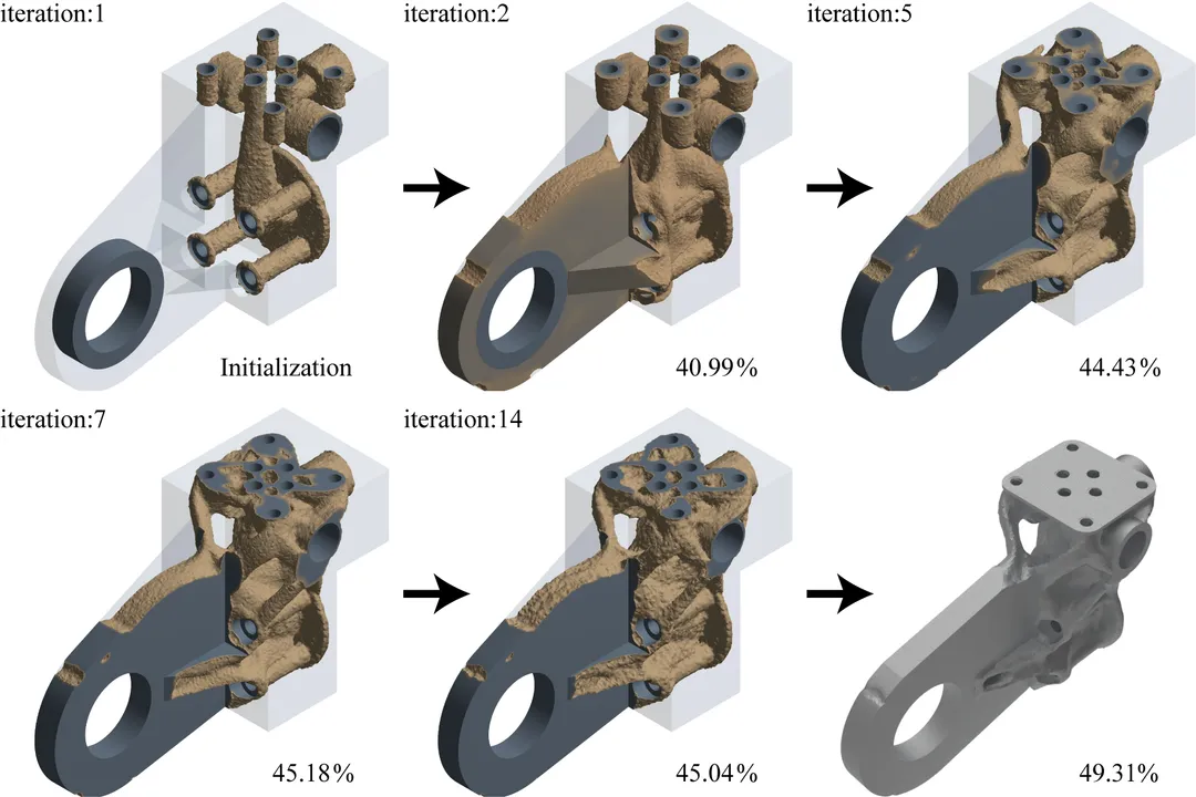
The choice of method can influence the speed and final quality of the design. While older methods often used penalization factors to drive densities toward zero or one, newer approaches continue to refine how material properties are mapped to structural performance within the iterative loop. The software then executes the simulation for many cycles, potentially hundreds or thousands, depending on the complexity of the model and the desired resolution.
# Monitoring Iterations
For a user running the process, monitoring the convergence is key. Software platforms provide outputs tracking the objective function—like compliance—over each iteration. Ideally, you want to see this value trend downward steadily, indicating the structure is becoming progressively stiffer relative to the material used. Sometimes, the convergence stalls, or the objective function fluctuates wildly, which might signal an issue with the initial constraints or a numerically unstable iteration. If the results appear nonsensical early on, it often means the initial design space was too restrictive or the loads were ill-defined. A common pitfall for newcomers is stopping the process too early; the initial iterations might look like disconnected noise, but if you allow the simulation to proceed, these sparse elements often connect into a coherent, load-bearing structure by iteration 50 or 100, assuming the setup is sound. Trusting the math through these sparse intermediate stages is part of developing expertise in this area.
# Output Handling
When the run concludes, the resulting file is usually a field of varying material densities. This output often requires post-processing before it can be sent to a machine. For example, material below a certain density threshold might be virtually removed, and the remaining surfaces smoothed or converted into a usable CAD format.
# Design Transition
The output of a topology optimization study is rarely the final, ready-to-manufacture part; rather, it is an idealized starting point. This transition from the optimized digital result to a tangible object requires significant engineering insight.
# Smoothing and Finalization
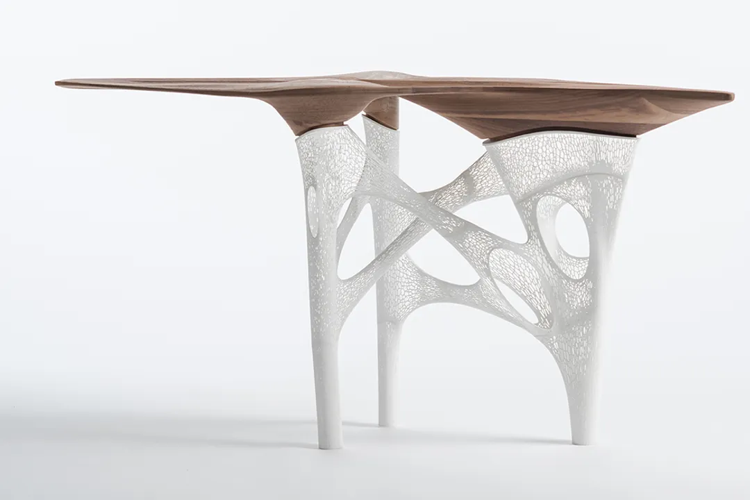
The raw topology result often has a somewhat porous or blocky appearance, a characteristic artifact of the underlying mathematical grid used for the calculation. Engineers must take this optimized geometry and refine it—perhaps by applying fillet radii, merging adjacent members, or simplifying complex joints—to ensure manufacturability and robustness in the real world. This refinement process must be done carefully to avoid removing the critical material paths identified by the optimization.
# Manufacturing Dependency
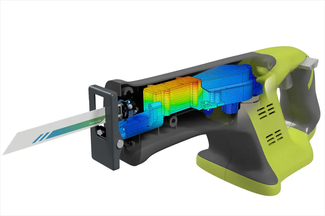
As noted, the method chosen for production heavily influences the final design. For metal parts requiring high strength, processes like Selective Laser Melting (SLM) or Electron Beam Melting (EBM) are common because they can handle the complex internal structures and lattice geometries that result from the optimization.
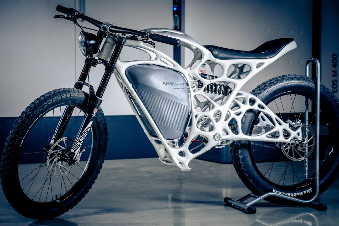
Consider a comparative scenario: if a bicycle frame component is optimized for casting, the final part will favor sweeping curves and uniform wall thicknesses suitable for mold filling. However, if the same loading case is run with constraints favoring Laser Powder Bed Fusion (LPBF), the resulting design will likely be a highly intricate, non-uniform skeletal arrangement featuring internal voids and interconnected struts, as LPBF can build these features layer by layer without concern for mold drafts or tool paths.

# Applications and Impact
Topology optimization is gaining traction across several demanding industries due to its ability to achieve unprecedented performance metrics.
# Lightweighting
The most immediate and quantifiable benefit is lightweighting. In aerospace and automotive sectors, reducing mass directly translates to lower fuel consumption and increased payload capacity. By replacing conventionally designed, over-engineered parts with optimized ones, mass reductions of 30% to 60% are frequently achievable while maintaining or even improving static and dynamic performance.
# Part Consolidation
Another significant advantage is part consolidation. In complex assemblies that traditionally required many individually manufactured components bolted or welded together, topology optimization can often design a single, integrated part that performs the function of the entire sub-assembly. This reduction in part count streamlines the supply chain, reduces assembly time, and eliminates potential failure points associated with bolted joints.
# Design Exploration
Furthermore, the technique serves as an exceptional tool for design exploration. It forces designers to think about function first—how loads travel through a structure—rather than being constrained by the limitations of traditional geometry creation. For instance, it has been successfully applied in designing heat exchangers, where optimizing the internal channels can significantly enhance thermal transfer efficiency compared to standard serpentine designs. While the initial barrier to entry is higher due to the need for specialized software and understanding of numerical methods, the resulting component performance often justifies the initial investment.
Related Questions
#Citations
Topology Optimization 101: How to Use Algorithmic ...
What is Topology Optimization?
Topology optimization
How to run a topology optimization
What is Topology Optimization? A Guide to Efficient Design ...
Topology Optimization
Topology Optimization With Generative Design
What is Topology Optimization?